Put a Shock in your Paint: Electrically-Conductive Coatings and Miracle Materials.

Electrically-conductive particles for use in coatings have taken a quantum leap forward in recent years. Revolutionary materials like carbon nanotubes (CNTs) and graphene possess 200 times greater strength than steel, with conductivity better than copper. This unique combination of strength, conductivity and high temperature resistance have the promise to impart exceptional properties in coatings that challenge the imagination. This article will discuss and contrast conductive materials with an emphasis on conductive nanomaterials and their potential advantage in coatings applications.


More than 200 conductive materials

That’s what you’ll find in Prospector®. Conductive additives, resins, pigments…Find materials faster with Prospector.

Click here to search for conductive coatings materials now


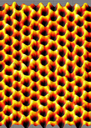
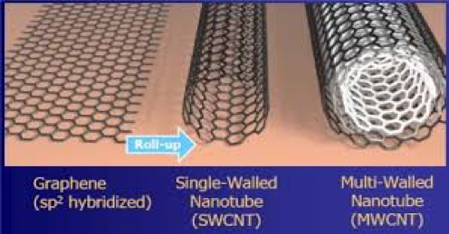
Other more commonly used electrically-conductive particles include conductive carbon black, graphite, quaternary ammonium salts, copper, aluminum, silver and combinations thereof. In addition to conductive particles, there are a number of conductive polymers that can provide conductive coatings that may be discussed in a future article. Surface resistivity of coatings is nearly independent of relative humidity. Figure 1 illustrates the structure of graphene, graphene is a two-dimensional structure and can be thought of as a single walled carbon nanotube in sheet form.

Scanning probe image of Graphene showing hexagonal two–dimensional arrangements of carbon atoms - learn more about conductive coatings in the Prospector Knowledge Center.
Figure 1 – Scanning probe image of Graphene showing hexagonal two–dimensional arrangements of carbon atoms
Conductivity = S/cm or S/mSurface resistivity = Ω/ (ohms per square)Surface resistance = ΩVolume resistivity = Ω x cmVolume (bulk) resistivity = (Resistivity x length x width) / height
Volume resistivity is a measure of sheet resistivity across defined thickness
Surface resistivity is the most common means used to characterize conductive coatings. ASTM D257 is the most widely-used standard for measuring surface resistivity.
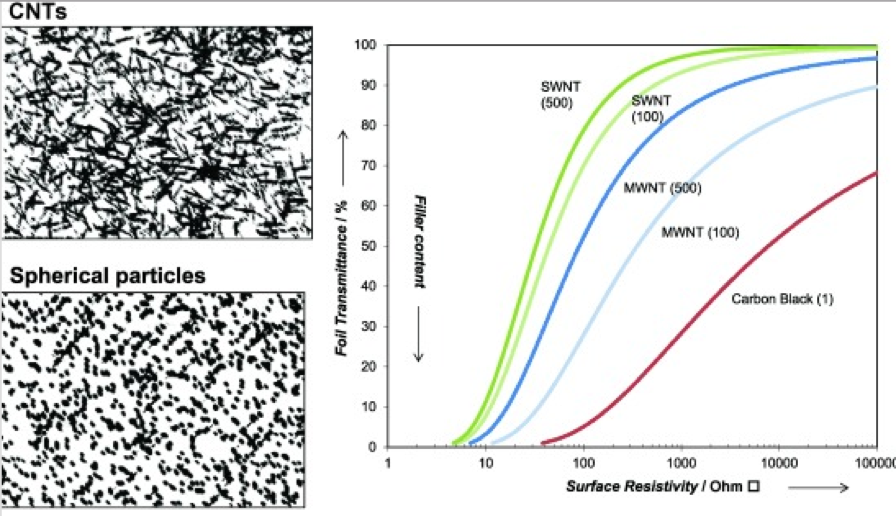
Percolation theory: As concentration of a conductive material in a coating increases, the conductivity will reach a point where the conductivity will abruptly increase once a critical concentration is reached.

Table 1 – Common Terminology of Conductive Materials

For electric current flow across a surface, surface resistivity (ohms/square) can be defined as the ratio of voltage drop per unit length, to the surface current per unit width.

Antistatic refers to the property of a material that inhibits triboelectric charging. Antistatic coatings have a surface resistivity of at least 1 X 10⁹, but less than 1 X 10¹².

Static dissipative coatings have:

  • a surface resistivity of 1 X 10⁵ ohms/sq. or
  • a volume resistivity of 1 X 10ohm-cm, but less than 1 X 10¹² ohm/sq. surface resistivity or
  • 1 X 10¹¹ ohm-cm volume resistivity.

Conductive coatings have a surface resistivity of less than 10ohm/sq., or a volume resistivity less than 104 ohm-cm.

Paint Film with 2% conductive particles on total weightASTM D257Surface ResistivityOhms/squareConsiderations
Quaternary Ammonium salt~ 1013Water sensitivityMigration to surface
Conductive carbon black~ 1010(antistatic)Color
Graphene~ 107(static dissipative)ColorDispersibilty
Carbon nanotubes (CNTs)< 103(conductive)ColorDispersibility

Table 2 – Films with conductive additives

Images of graphene, single-walled carbon nanotube, and multi-walled carbon nanotube. Learn how this technology is applied to conductive coating formulation.
Figure 2 – Images of graphene, SWNCNT, MWCNT

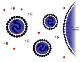
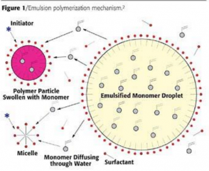
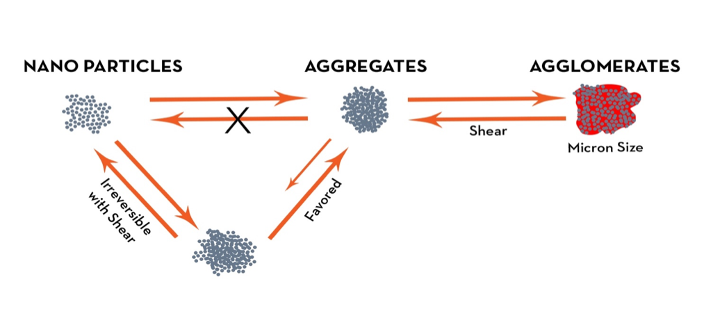
An important aspect of obtaining optimum conductivity from both graphene and CNTs for water or solvent-borne applications is to ensure that the dispersion is optimal and stabilized. If graphene and/or CNTs are not effectively dispersed, the particles will not be adequately separated and form bundles of particles. These materials tend to self-associate and form clusters, which in turn do not provide adequate connectivity to support optimum conduction of an electric current.

To overcome this issue, in many cases nonconventional means of dispersion are employed. Sonication is one such method that untangles nanoparticles, and thus provides the connectivity to support a current (percolation).

The agglomeration of graphene and CNTs is known to have a major impact on the percolation threshold and thus electrical conductivity of their nanocompositions. The interface between the conductive materials also has a profound effect on conductivity. The percolation threshold is the threshold at which the concentration of conductive nanomaterial of the composition displays an abrupt transition from insulator to a conductor. The aspect ratio of a conductive material (width:height) also plays an important contribution to the percolation threshold (lower aspect ratios favor conductivity).

The reason for the conductivity of graphene and more so CNTs is their extensive network of sp2 bonds and stacking of their pi bonds.

Graphene can be described as a single layer thickness of graphite. Graphite is also electrically conductive and available in different purities as well as amorphous or crystalline forms.

One of the other reasons why nanoparticles such as graphene and CNTs are so conductive is that they are ultrasmall. As the dimension of a particle decreases, the ratio of surface area to volume increases quite dramatically. Larger surface area produces greater interaction of particles and higher attractive forces. For example, a surface area over 100nm in size normally defeats the advantage that nanoparticles provide to enhance performance.

Percolation Threshold and particle structural effects on surface resistivity. Learn how this impacts the formulation of conductive coatings in the Prospector Knowledge Center.
Figure 3 – Percolation Threshold and particle structural effects on surface resistivity
Nanoparticles and Agglomeration - learn how they impact the formulation of conductive coatings in the Prospector Knowledge Center.
Figure 4 – Nanoparticles and Agglomeration

The proper use of conductive nanoparticles in coatings can impart multiple beneficial properties. Stabilization of dispersed nanoparticles is essential to optimize the full benefits of these materials. Secondly, formulations utilizing nanoparticles must be tailored to provide proper acceptance, rather than as a drop-in to achieve a desired property.

MaterialResistance Ohm-M
Graphite1 X 10-5
Brass0.9 X 10-7
Platinum0.98 X 10-7
Silver1.6 X 10-8
Aluminum2.8 X 10-8
Copper1.7 X 10-8
Zinc5.5 X 10-8

In addition to their electrical properties, graphene, graphite and CNTs provide good stability at high temperatures. Furthermore, due to their unique molecular structure, when properly dispersed, they can also enhance mechanical properties. The temperature stability of CNTs in air is reported to be 750° C, graphene and graphite in excess of 600° C.

Applications for future coatings using the next generation of conductive materials will include:

  • coatings to prevent electronic discharge for electrical applications
  • communication equipment
  • consumer electronics
  • computer equipment
  • flexible electrical equipment
  • electronic applications requiring high temperature resistance and enhanced mechanical properties.

In summary, properly formulated coatings utilizing conductive particles and especially conductive nanoparticles can achieve performance attributes heretofore not obtainable by other means.

References and further reading:

Cathodic Electrocoat: Priming the Way to Unsurpassed Product Finishing Performance

The global electrocoat market is estimated to grow from USD 3.08 billion in 2016 to USD 3.80 billion by 2021, at a CAGR of 4.34 percent between 2016 and 2021. This market is witnessing moderate growth because of demand for e-coat from the end-use industries such as automotive and appliances1.

Electrocoating is a process that uses an electrical current to deposit an organic coating from a paint bath onto a part or assembled product. Due to its ability to penetrate recesses and thus coat complex parts and assembled products with specific performance requirements, electrocoat is used worldwide throughout various industries to coat a wide swath of products including those in automotive, appliance, marine and agriculture. Electrocoat, and specifically cathodic electrocoat, has enabled a dramatic improvement in corrosion resistance over that offered by anodic electrocoat or other more conventional methods of coating.

Cathodic electrocoat is available in multiple technology types, most notably is epoxy cathodic and acrylic cathodic.

  • Acrylic cathodic is expected to experience the highest growth in the e-coat market. Cathodic acrylic e-coat is typically used in applications that require UV durability as well as corrosion protection on ferrous substrates. It is also used in applications where light colors are required.
  • Cathodic acrylic e-coat is available in a wide range of glosses and colors to provide both exterior weathering and corrosion protection. Acrylic cathodic is used as a one-coat finish for agricultural implements, garden equipment, appliances and exterior HVAC.

The application of electrocoat involves four steps:

  1. Pretreatment2: After the parts are cleaned, a pretreatment is applied to prepare the metal surface for electrocoating.
  2. Electrocoat Application: Positively charged cathodic paint is deposited on the electrically conductive substrate from a cathodic paint bath using direct current. The positively charged paint is deposited at the negatively charged cathode where reduction takes place.
  3. Post Rinses: Parts are rinsed to reclaim undeposited paint solids.
  4. Bake: Paint is baked to thermally cross-link the paint and volatilize water as well as any residual organic solvents.

In step 2, paint particles are deposited on the surface of the electrically conductive substrate to form an insulating film.  The rate of the film deposited diminishes with time as the conductivity of the paint surface has an insulating effect as the film increases in film thickness. At this point the deposited film has very little water and solvent present so the water post rinses (step 3) do not have a negative effect on the deposited film. The coated substrate is then baked to eliminate water and remaining volatile as well as to crosslink the polymeric film.

Cathodic Electrodeposition - learn more about cathodic electrocoating in the the Prospector Knowledge Center
Figure I: Cathodic Electrodeposition

As figure I indicates, in cathodic electrodeposition, the positively charged paint is attracted to the negatively charged cathode where reduction occurs, resulting in the liberation of hydrogen gas. At the anode, oxidation occurs with the accompanying release of oxygen. The deposited paint film is coalesced into a relatively insoluble paint film and after one or more water rinses, the deposited paint film enters a bake oven to enable the crosslinking of the cathodic paint film.

The advantages and disadvantages of cathodic electrocoat include:

  • Excellent corrosion resistance, even at lower film thicknesses
  • Offers excellent resistance to bimetallic corrosion (when dissimilar metals are in contact)
  • Frequent color change is not practical
Cathodic Electrocoat Deposition example - learn more in the Prospector Knowledge Center
Electron flow in cathodic electrocoat deposition - learn more in the Prospector Knowledge Center.

Many cationic epoxy electrocoat resins are comprised of a Bisphenol A based epoxy resin comprised of amine groups that are neutralized with a low molecular weight acid such as formic, acetic or lactic acid. Since the coating bath has a pH of slightly below 7, bath components are comprised of stainless steel or other corrosion resistant materials to prevent rust formation.

The most common crosslinker is a blocked isocyanate, so once the coating is baked, the blocked isocyanate is activated and reacts with available hydroxyl and amine groups. Other components of a typical electrocoat bath include pigment, filler pigment, water, solvent and a low level of modifying resins such as plasticizers and flexibilizersflow modifiers and catalysts.

Cross section of automotive coating system - learn more in the Prospector Knowledge Center.
Cross section of automotive coating system


Ecoat is used because it provides superior corrosion protection as it coats surfaces that are inaccessible by conventional means. Film thickness is uniform without any defects such as sags, runs or edge beads. Electrocoat is also very cost effective as it provides nearly 100 percent material utilization with good energy efficiency and a relatively low cost per square foot of applied coating.

Throwpower is the ability of an electrocoat to penetrate into “hard to reach” areas, such as the inside of a hollow metal object. Dependent on applied voltage, bath solids, conductivity, deposition time, bath temperature, solvent levels, and proper tank agitation, deposition time, throwpower and coating appearance can be optimized.

A simple dip-applied coating cannot effectively coat the interior of complex shaped parts, as during the bake process, the water/solvent has a washing effect in the interior portions of the part that prevents adequate film build. At the time an electrocoated object is removed from the bath, most of the water and solvent is squeezed from the electrocoat so that during the bake the washing effect is minimal as compared to that of a simple dip-applied coating.

The film build of electrocoat paint is self-limiting as the film becomes more insulative as the thickness of the film approaches its maximum. Higher voltage and longer immersion times will permit higher film builds until the maximum possible film build is reached, which is normally about 1.0 mil and 1.2 mils.

Voltage is normally between 225 and 400 volts. If the voltage is too high, there will be film rupture of the coating applied to the outer surfaces. This is called the rupture voltage. At a sufficiently high voltage, the current will break through the film, leading to gas generation under the film (hydrogen for cathodic and oxygen for anodic).

Other factors that affect film build include bath temperature and conductivity. Immersion times are normally on the order of 2-3 minutes.

In summary cationic electrocoating is expected to grow at a faster rate than that of more conventional product finishing processes as it provides excellent corrosion protection for complex shapes, low volatile organic content and lastly acrylic cationic electrocoat also offers resistance to UV light for experior applications.

To read the rest of the article please click here to head over to UL Prospector.

__________

Ron Lewarchik, Author of article & President of Chemical Dynamics

As a contributing writer, Ron pens articles on topics relevant to formulators in the coatings industry. He also serves as a consultant for the Prospector materials search engine, advising on issues related to optimization and organization materials within the database.

Overcoming Paint Film Defects: Causes and Remedies

Paint film defects can appear during or immediately after application or become more apparent after the coating is cured. While there is no standard convention for the nomenclature of film defects, this article will separate film defects into the two categories mentioned above.

Crawling, crafters, crazing - a variety of paint defects can occur after application or curing. Learn the causes and solutions here.
Example of crazing.
Copyright: paylessimages / 123RF Stock Photo

Paint film defect causes

The largest number of paint defects is from dirt particles1embedded in the paint. Most other paint defects are the results of:

  • lack of cleanliness
  • surface preparation
  • application error
  • attention to detail

Surface tension

Many coating defects are related to surface tension issues. Surface tension is the elastic tendency of liquids that make them acquire the least surface area possible. This occurs when the forces at the interface of a liquid differ from those within the liquid, attributed to uneven force distribution of molecules at the surface. A common unit of surface tension is dynes/cm2 (force/unit area).

For example, applying a coating with a higher surface tension than the substrate may cause dewetting, crawling, pinholing, holidays and telegraphing.

Likewise, the difference in surface tension at the paint surface can result in cratering or fisheyes.

Table 1: Surface tension of paint Solvents

Solvent Surface Tension Dynes/cm
Water 72.8
Toluene 28.4
Isopropanol 23.0
n-Butanol 24.8
Acetone 25.2
Methyl propyl ketone 26.6
Methyl amyl ketone 26.1
PM acetate 28.5


Table 2: Liquid surface tension of Polymers used to reduce surface defects

Polymer mj/m2
Poly(dimethylsiloxane) 22.6
Poly nButyl Acrylate 33.7
Poly nButyl Methacrylate 31.2


Highly polar molecules (e.g. water) have a higher surface tension than less polar materials (see Tables 1 and 2). Surface defects can often be reduced or eliminated by using small amounts of additives with low surface tension such as polydimethyl siloxanes (DMS), poly butyl acrylate or poly 2-ethyl hexyl acrylate. These additives tend to migrate to the surface to help flow and leveling.

Table 3: Defects that can occur during or soon after application

           Defect Appearance                Causes          Remedy
Crawling Uneven film thickness, dewetting High surface tension paints applied to a substrate with lower surface tension. For example, paint on steel with oil on the surface
  • Proper surface cleaning of metallic or plastic surfaces
Craters/fish eyes Small round depressions in the surface of the coating Small particles of a low surface tension contaminant (e.g. oil, grease, silicone oil, wax) on the substrate or that embeds in the coating
  • Proper spray booth air filtration and the contaminant elimination.
  • The addition of surface wetting agents such as DMS and/or polyacrylates with a low glass transition (Tg).
Crazing, cracking Small cracks formed in the coating. This can occur on recoat or if coating is applied to solvent sensitive plastics Application of coatings on plastics where the paint contains strong solvent that solvates the underlying coating layer or plastic substrate
  • Use solvent that will not crack or craze the plastic.
  • Test spot resistance of substrate with suitable solvent.
Dirt, contamination Small raised imperfections in the surface of the coating
  • Surface not carefully cleaned.
  • Dirty spray booth and/or booth filters.
  • Pressure in the spray booth too low.
  • Unsuitable work clothes.
  • Inadequate paint filtration
  • Ensure cleanliness of the environment where the coatings are applied
Loss of gloss, blush Areas of low gloss or a white haze Humidity condenses on the wet paint due to the cooling effect of solvent evaporation when the substrate temperature is below the dew point. Causes:

  • Unsuitable reducers
  • Poor air circulation in drying oven
  • Film thickness too high or low
  • Proper humidity control


Mottling Uneven appearance of metallic paints
  • Dirty spray gun nozzle
  • Incorrect air pressure
  • Incorrect reducer
  • Faulty spray technique
  • Incorrect spray viscosity
  • Use proper viscosity cup to obtain spray viscosity.
  • Clean and maintain spray guns on a regular basis.
  • During application maintain spray gun parallel to the substrate and maintain correct distance from gun to substrate.
  • Follow Technical Data Sheets instructions.
Poor hiding · Uneven paint coverage
  • Nonuniform substrate surface
  • Uneven or inadequate paint coverage to mask the substrate color
  • Uniform and sufficient paint application to obtain proper hiding.
Runs and sags Drips and sags
  • Paint applied too thick or too wet to a vertical surface and the force of gravity overcomes the forces resisting the downward flow of paint (viscosity).
  • Temperature too low to enable proper solvent evaporation (solvent born paint), or humidity too high (waterborne paint).
  • Adjust low shear viscosity of paint with appropriate thickener.
  • Use proper reducer and viscosity adjustment for environmental conditions.
  • Adjust spray gun and apply thinner wet coats. If a waterborne paint, apply paint in a lower humidity environment.
Skips/holidays Incomplete paint coverage
  • Paint applied too thin
  • Minute areas on the substrate surface of low surface tension, causing inadequate film flow and coverage.
  • Proper paint application and ensure surface cleanliness.
Striping, banding Stripes of uneven paint appearance (e.g. differing color) Uneven paint application
  • Use proper viscosity cup to obtain spray viscosity.
  • Clean and maintain spray guns on a regular basis.
  • During application, maintain spray gun parallel at the correct distance to the substrate and maintain
Telegraphing Highlighting of the surface of the coated substrate through the coating. Such defects as fingerprints, sand scratches and water spots on the substrate become visible on the coating surface Coating with high surface tension applied to a substrate with lower surface tension. e.g. Fingerprints or silicone oil on a substrate surface.
  • Ensure that the substrate is thoroughly clean and absent of low surface tension oils and fingerprints.
Wrinkling, lifting, aligatoring Upon applying an overcoat, the existing paint film shrivels, wrinkles or swells; may also occur during drying. Solvents in the new paint swell the underlying paint finish.
  • Allow sufficient cure times of underlying paint
  • Ensure that the new paint is compatible with the undercoat
  • Proper application of the new paint (not too wet).


Table 4: Defects that are more apparent after cure

Defect Appearance Causes Remedy
Air entrapment Similar to solvent popping or bubbles Paint pump sucking air when paint level is low. In two component urethanes, moisture present reacts with isocyanate to cause CO2 generation.
  • Proper attention to paint line conditions.
  • Ensure use of urethane grade solvents and proper spray gun air filtration through desicant.
  • Addition of moisture scavenger in paint.
Barnard Cells Hexagonal pattern in the surface of a cured paint film. Convection pattern from pigment segregation as a result of surface tension differentials Adjust formulation to overcome flooding and differential surface tension at surface
Blisters Bubbles near the surface of a film during oven cure that do not break through the surface. Viscosity of the surface of the film increases to a high level, trapping the volatile solvent at a lower level.
  • Proper oven staging to enable slow release of solvent.
  • In an acid catalyzed system, use an acid salt to slow the cure and enable solvent release.
  • Increase flash time before bake.
  • Use slower evaporating solvent.
  • For spray application, apply additional thinner coats to build film rather than fewer thick coats.
  • For waterborne coatings, use a dehydration bake lower than the boiling point of water, followed by a second bake to cure.
Orange peel Rough surface that resembles the surface profile of an orange Paint applied at high viscosity or under conditions deleterious to proper flow and leveling.
  • Adjust paint to proper viscosity with correct reducer per technical data sheets.
  • Apply at proper fluid delivery rate and atomizing air pressure.
Solvent pop Broken bubbles at the surface of a film that do not flow out during oven cure Viscosity of the surface of the film increases to a high level, trapping the volatile solvent at a lower level. The bubbles break the surface when the solvent volatilizes.
  • Proper oven staging to enable slow release of solvent.
  • In an acid catalyzed system, use an acid salt to slow the cure and enable solvent release.
  • Increase flash time before bake.
  • Use slower evaporating solvent.
  • For spray application, apply additional thinner coats to build film rather than fewer thick coats.
  • For waterborne coatings, use a dehydration bake lower than the boiling point of water followed by a second higher bake to cure.
  • Lastly, the use of lower Tg resins along with lower dry film thickness decrease popping.


Search Prospector for formulating remedies to overcome paint film defects:

Defect Remedy material
Crawling and substrate wetting
Craters and fish eyes
  • PDMS
  • polyalkyl acrylates
Runs and sags
Telegraphing
Air entrapment
Solvent pop, blisters For melamine cure systems:


To read more, please click here to head over to UL Prospector.

__________

Ron Lewarchik, Author of article & President of Chemical Dynamics

As a contributing writer, Ron pens articles on topics relevant to formulators in the coatings industry. He also serves as a consultant for the Prospector materials search engine, advising on issues related to optimization and organization materials within the database.

Architectural Coatings that Reduce Heating and Cooling Costs

In order to appreciate architectural coatings that reduce heating and cooling costs, it is important to understand the fundamentals regarding US energy consumption. According to the U.S. Energy Information Service, 40 percent of all US energy consumption is used for heating and cooling residential and commercial buildings. For homeowners, 25 percent of their average energy bill is for cooling. Considering these facts, consumers appreciate any efficiencies coatings formulators can offer.

Heat transfer mechanisms

Prior to considering how coatings can be engineered to save heating and cooling costs, it is instructive to examine heat transfer mechanisms: radiation, conduction, and convection.

Radiation

As figure 1 indicates, radiation is the emission and propagation of light energy in the form of rays or waves through space:

architectural-fig1
Figure 1 – Radiation light spectrum1

As figure 2 illustrates, pigments can absorb or reflect solar infrared energy based on their color.  For example, if the pigment absorbs infrared (IR) energy (such as conventional darker pigments), we see heat build-up of the coated substrate. If the pigment reflects IR light (such as white and lighter colors), we see a lower increase in temperature.

To illustrate, the surface of a steel building at an ambient air temperature of 20° C will remain at about 20° C when painted white, whereas the surface will be about 35° C when painted black.


To read the rest of the article please click here to head over to UL Prospector.

__________

Ron Lewarchik, Author of article & President of Chemical Dynamics

As a contributing writer, Ron pens articles on topics relevant to formulators in the coatings industry. He also serves as a consultant for the Prospector materials search engine, advising on issues related to optimization and organization materials within the database.

Metal Surface Treatment – The Key to Successful Performance

No matter what metal surface needs to be painted, successful performance begins with proper cleaning and surface preparation. This article will concentrate on the essential issues in the manufacturing process necessary to ensure successful metal treatment and resultant coating performance. As there are hundreds of surface treatments, we will address the major factors that influence phosphate metal pretreatment which are one of the most widely used pretreatment chemistries. Phosphate treatments are used on steel, zinc and aluminum substrates.

The pretreatment process for metal surfaces provides multiple benefits as it is the foundation of the paint layering system. A quality metal treatment process enhances adhesion between the metal and paint layers by providing a more uniform surface and provides greater corrosion resistance with less undercutting of the paint film.

Table I – Typical Spray or Immersion Process involved in Phosphate Pretreatment

PROCESS STEP ORDER PURPOSE CHEMICALS POTENTIAL PROBLEM(S)
1. Cleaning (see Figs I & II) Remove soils, mill oil, lubricating oil and drawing compounds, dissolution of metal oxide(s), precipitate hard water deposits Alkaline Cleaner
  1. Incomplete removal, synthetic oils can be more difficult to remove than natural oils
  2. Contaminated cleaning process, cleaning chemicals spent
  3. Temperature too low
  4. Poor tank maintenance
  5. Inadequate mechanical action
  6. Change in time, temperature, pressure (for spray cleaner) or cleaner concentration
2. Water rinse(s) Remove residual detergents and deposits Quality tap water and/or reverse osmosis (R/O) water
  1. Drag out water sensitive deposits from the cleaning process
  2. Tap water that contains hard water may deposit moisture soluble compounds on the metal surface
3. Rinse Conditioner (see Fig III) For Phosphate- Aids in the development of the proper phosphate crystals on the metal surface Colloidal Titanium Salts and additives Destabilization of the Ti Colloid:

  1. pH too low or too high
  2. High heat
  3. Contamination
  4. Poor water quality (too hard)
4. Phosphate Step (See Fig IV) Forms a microcrystalline coating to enhance paint adhesion and corrosion resistance
  1. Phosphoric and nitric acid
  2. Zn, Ni, Mn Fe cations
  3. Fluoride, Surfactants and accelerator
  1. Must continually remove iron phosphate sludge for proper control
  2. Ensure optimum recirculation rate for tank process or spray nozzle pressure for spray process
5. Rinse Stops the chemical reaction on the metal surface Water Water must be clean
6. Post Rinse Fill voids in pretreatment Hexafluorozirconqic acid Proper control of pH, time , temperature and pressure (spray)
7. Deionized (D.I.) Rinse(s) Remove any residual chemicals and to provide a clean surface for coating D.I. Recirculating rinse, followed by a D.I rinse Carry over of chemicals and other contaminants from previous steps. Must ensure that D.I. water quality is maintained


To read the rest of the article, written by Ron Lewarchik, please click here to head over to UL Prospector.

__________

Ron Lewarchik, Author of article & President of Chemical Dynamics

As a contributing writer, Ron pens articles on topics relevant to formulators in the coatings industry. He also serves as a consultant for the Prospector materials search engine, advising on issues related to optimization and organization materials within the database.

The Fundamentals of Emulsion Polymerization

This article will detail the fundamentals of emulsion polymerization. Emulsion polymerization was developed by The Goodyear Tire & Rubber Company in the 1920s. The emulsion-polymerization process results in a latex particle, which is a dispersion of polymer in water. Waterborne coatings that primarily use emulsion polymers are the largest type of coating technology used on a global basis and are expected to continue to grow as a percent of the total coatings market.

In emulsion polymerization, monomers are first dispersed in the aqueous phase. Initiator radicals are generated in the aqueous phase and migrate into the soap micelles that are swollen with monomer molecules. As the polymerization proceeds, more monomers migrate into the micelle to enable the polymerization to continue.

figure1

Since only one free radical is present in the micelle prior to termination, very high molecular weights are possible., on the order of 1,000,000 or higher. Unlike solution polymers, the viscosity of latexes are governed by the viscosity of the medium the particles are dispersed in (continuous medium). Chain transfer agents are added to control the molecular weight. The resultant emulsion particle is an oil in water emulsion. monomer in the aqueous phase.

A less commonly used emulsion technique called the inverse emulsion-polymerization process involves dispersing an aqueous solution of monomer in the nonaqueous phase.

Emulsion polymerization can occur using a batch process, semi-continuous process or continuous process. Commerciallatex polymers are made using a semi-continuous or continuous process rather than a simple batch process because the heat evolved in a simple emulsion batch process would be uncontrollable in a large reaction vessel. In the semi-continuous batch process, monomers and initiators are added in proportions and at a controlled rate so that rapid polymerization occurs. In this method, the monomer concentration is low, also called under-starved monomer conditions, to facilitate temperature control. It is also common to start the polymerization using a seed latex.

In the continuous process, the reaction system is continuously fed to, and removed from, a suitable reactor at rates such that the total volume of the system undergoing reaction at any instant is constant.


To read the rest of the article, written by Ron Lewarchik, please click here to head over to UL Prospector.

__________

Ron Lewarchik, Author of article & President of Chemical Dynamics

As a contributing writer, Ron pens articles on topics relevant to formulators in the coatings industry. He also serves as a consultant for the Prospector materials search engine, advising on issues related to optimization and organization materials within the database.


Using Effect Pigments for Limitless Coatings Design Possibilities

Effect Pigments, UL Prospector, Ronald Lewarchik, 5/2016: Effect pigments provide an infinite array of colors and effects that enable unlimited design possibilities for coatings. These effects include the illusion of flickering lights, metallic reflection, interference sparkle and color variation and luster that changes with the viewing angle and light source.

They are used in a variety of coatings, including those in automotive, monumental and smaller buildings as well as other industrial and product finishing applications. Pigments may be broadly classified by their ability to reflect light: absorption, metallic and interference.

Conventional organic and inorganic pigments are classified as absorption pigments, because they absorb certain wavelengths of the incident light that strikes their surface. The sensation of color is produced by the remaining component of the reflected visible light that produces the color we observe.

For example, a quinacridone red pigment reflects the portion of the light that produces a red color and absorbs the rest of the light energy. Titanium dioxide reflects all of the light and absorbs none, while carbon black absorbs all and reflects none. Due to their ability to absorb light, absorption pigments do not display a metallic luster or iridescence and are thus one dimensional in their ability to interact with light.

Metallic pigments consist of tiny flat pieces of aluminum, bronze, zinc, copper, silver or other metals that reflect light and thus create a metallic luster. These pigments are two- dimensional or metallic pigments.

Get Material Data Interference pigments consist of various layers of, for example, a metal oxide deposited onto mica, a natural mineral. Light striking the surface of these pigments is refracted, reflected and scattered by the layers that make up the pigment. Through a superimposition (or interference) of the reflected rays of light, a changing array of color is created, with the most intense color seen at the angle of reflection.

Effect pigments are unique in respect to how they interact with light due to their geometry which is normally a platelet with a high aspect ratio (ratio of width to height). Depending upon the specific technology, a wide variety of colors and effects can be created, such as interference shimmers, color travel effects or metallic reflection.

To read the rest of Ron’s article, click here to head over to UL Prospector.

Acrylic Resin Fundamentals

Acrylic Resin Fundamentals, UL Prospector, Ronald Lewarchik, 4/2016:

Coatings utilizing acrylic resins are the leading polymer technology in the coatings industry. Historically alkyd finishes have held the leading position in coatings for decades. Acrylics are utilized in architectural coatings, product finishes for original equipment manufacture including automotive (OEM) and refinish, as well as special-purpose coatings.

Acrylic resins are primarily based on acrylate and methacrylate monomers and provide good weather resistance, resistance to hydrolysis, gloss and color retention in exterior applications. Due to their versatility and performance, acrylic coatings account for over 25% of all coatings and global sales approaching $25 billion. Acrylic resins can be thermoplastic or thermosett and are used in organic solvent born, waterborne, powder and radiation-curable coatings

Table I – Tg of Nonfunctional Homopolymers

Three broad classes of liquid coatings utilizing acrylic resins include thermoplastic, thermoset and waterborne. Many acrylic resins may also include other vinyl monomers such as styrene or vinyl acetate primarily to reduce cost. Acrylic monomers have a lower Tg than their analogous methacrylate monomers (for example compare the Tg for n-butyl acrylate versus n-butyl methacrylate see Table I and Table II). As Table II suggests, the glass transition temperature of the monomers selected for synthesis of a resin can be selected to enhance multiple properties that may include weather resistance, moisture resistance, oxygen permeability, flexibility reactivity, cure and hardness. In addition, acrylics can be functionalized with a variety of monomers to provide improved adhesion to metal, or to react for example with aminoplast or isocyanate crosslinkers.

acrylics_table_2 
Table II Relationship of Tg to Physical Properties

Thermoplastic acrylic polymers (TPA) in general have excellent properties including exterior durability. Such resins were widely used in automotive OEM and Refinish topcoats from the 50’s to the 70’s, but their use has dramatically declined due to the high molecular weight necessary to provide properties, they require a high amount of organic solvent to enable air atomized spray application. Accordingly these paints apply at about 20% weight solids. Thermoplastic resins typically use a high level of methyl methacrylate in their polymer backbone to provide excellent hardness and exterior durability.

Figure I – Structure of poly MMA and poly MA 
Figure I – Structure of poly MMA and poly MA

Thermosetting acrylic resins (TSA) are designed with functional monomers to either react with themselves when exposed to heat or moisture, or with that of a cross-linker to form a cross-linked film. Thermoset resins as a group are lower molecular weight and thus have higher application solids. Once cross-linked, as a class they offer films with excellent resistance to organic solvents, moisture and UV light and do not soften appreciably when exposed to moderately high temperatures as thermoplastics do.  An example of acrylic monomers with functional groups that can be used to functionalize acrylic polymers to provide properties such as crosslinking, self-crosslinking, improved adhesion or pigment wetting are provided in Table III.

Table III – Functional Acrylic Monomers 
Table III – Functional Acrylic Monomers

Being able to functionalize an acrylic resin with a wide range of reactive moieties provides the ability to tailor the performance of the resin backbone to provide improved adhesion over a variety of substrates, improved pigment wetting and/or the ability to provide crosslinking or self-crosslinking. Other acrylic monomers are also available to impart sulfonic acid, or phosphoric acid functionality to the acrylic resin.

Being able to functionalize an acrylic resin with a wide range of reactive moieties provides the ability to tailor the performance of the resin backbone to provide improved adhesion over a variety of substrates, improved pigment wetting and/or the ability to provide crosslinking or self-crosslinking. Other acrylic monomers are also available to impart sulfonic acid, or phosphoric acid functionality to the acrylic resin.

Carbamate functional acrylics can also be made for example by reacting an isocyanate functional acrylic with hydroxypropyl carbamate. Many of the acrylics in the category of functionalized acrylic resins are used in automotive OEM and refinish clearcoats to provide an excellent combination of mar resistance, chemical resistance and light stability.


To read the rest of Ron’s article, click here to head over to UL Prospector.


Basics of Alkyd Resin Technology

Mastering the fundamentals of Alkyd Resin Technology

Although alkyds are no longer the largest volume resin type used in coatings, they still play a significant role in the coatings industry, not only because of their versatility, but also because they employ a significant amount of renewable material.

The term alkyd is derived from alcohol and acid.

Alkyds are prepared from the condensation reaction between polyols, dibasic acids and fatty acids. The fatty acid portion is derived from vegetable matter and thus is a renewable resource. Key performance features of alkyds include their ability to offer improved surface wetting (from the bio-based fatty acid portion of substrates and pigments) and lower cost (also primarily from the fatty acid portion). The most widely used polyols include glycerol, pentaerythritol and trimethyol propane whereas the most widely used dibasic acids are phthalic anhydride and isophthalic acid.

Alkyd figure one updated

Naturally-occurring oils are in the form of triglcerides. Triglycerides are triesters of glycerol and fatty acids. Triglycerides can be drying oils, but many are not. The reactivity of drying oils with oxygen results in 1,4 –dienes. The naturally-occurring oils are comprised of mixtures of mixed triglycerides with different fatty acids as part of the glyceride molecules.

Some of these glyceride molecules are comprised of a higher percentage of fatty acids with a greater amount of non-conjugated unsaturation with diallylic methylene groups and result in improved drying capability. For example, linoleic acid has one active diallylic group (-CH=CH – CH2 – CH=CH -), whereas linolenic has two active methylene groups. Also, to increase drying speed, alkyds can be modified with vinyl toluene or styrene to increase the Tg and thus reduce the time required to reach a given hardness. If the amount of oil in an alkyd is over 60%, it is called a long oil alkyd. If it’s between 40 and 60%, it’s known as a medium oil alkyd, and those with less than 40 are considered short oil alkyds. The formula for calculating the percent oil length based on the amount of fatty acid is as follows:

Alkyd 2

In addition to the amount of oil as well as the selection of the alcohol and acid functional components, the type of oil has a profound effect on the dry time and performance.

Fatty acids are further categorized into drying, semidrying and non-drying. Non-conjugated oils are considered drying oils if their drying index, as calculated as follows, is more than 70. The higher the amount ofLinolenic and Linoleic content, the higher the drying index:Alkyd 3

Although drying speed is improved as the % linolenic increases, the rate of yellowing for exterior white coatings is also greater. Accordingly, alkyds using safflower and sunflower oils which provide improved resistance to yellowing as a result of their lower linolenic content.

Alkyd 4Alkyd 5

In addition to classifying alkyds by their oil length and the type of fatty acid present, alkyds are also classified into oxidizing and non-oxidizing categories. Oxidizing alkyds crosslink through a complex multistage auto-oxidation mechanism, whereas Non-oxidizing alkyds do not crosslink and are thus thermoplastic unless their available hydroxyl groups are crosslinked with an aminoplast (heat cured) or isocyanate crosslinker (ambient cured).

To read the rest of the article, written by Chemical Dynamics’ President, Ron Lewarchik, click over to UL Prospector here.

UV-LED Curable Coatings Offer a High-Speed Light Curing Process

UV-LED Curable Coatings offer a high-speed light curing process with a number of advantages over more conventional cure processes. Multiple advantages include High speed, lower energy requirements, little or no VOC, less production space, less dirt collection, high quality finish, rapid processing as well as instant on-off with some UV light technologies also expedite production and energy savings. UV Curable paint finishes have existed since the 1960’s and are based on polymerization reactions including free radical and cation-initiated chain-growth polymerization. As the majority of coatings for UV cure coating utilize free radical polymerization (>90% of market), this article will focus primarily on free radical polymerization initiated by a photoinitiator (Fig. 1):

Figure 1 Rev

The types of unsaturation used in UV/EB cure coatings are provided in Table I, with by far the largest type being acrylate.

Table I – Type of Unsaturation used in UV/EB Cure

Photoinitiator

considerations primarily include two different characteristics of the photoinitiator’s absorption curve. First, is the maximum wavelength (Lambda Max) of light that is absorbed by the PI and second, the strength of this absorption (molar extinction coefficient). Photoinitiators developed for curing pigmented films normally have higher molar extinction coefficients at longer wavelengths between 300 nm to 450 nm than those for curing clear formulations. To maximize cure and efficiency, the PI’s absorbance must match the light output of the lamp as different lamps have different spectral outputs (see Table I). Longer wave- length light is also essential to enhance cure in thicker coatings. Newer PI’s have also enabled the formulation of pigmented coatings in addition to that of clear coatings. The general cure considerations influenced by color, PVC, pigment particle size and film thickness are summarized in Fig. 2:

Figure 2 – UV Cure Considerations
Figure 2 – UV Cure Considerations. Image: Ciba – Geigy literature

There are two main types of free radical photoinitiators, Type I and Type II. Type I photoinitiators undergo cleavage upon irradiation to form two free radicals. Normally only one of these free radicals is reactive and thus initiates polymerization. 1-hydroxy-cyclohexylphenyl-ketone is a widely used Type I PI. Type II photoinitiators form an excited state upon irradiation, and abstract an atom or electron from a donor molecule (synergist). The donor molecule in turn initiates polymerization. An example of a widely used Type II photoinitiator is benzophenone. Tertiaryamines are typically used as synergists as they react with benzophenone, and also retard the inhibition of polymerization by oxygen. Acrylated tertiary amine compounds are used when odor and extractables are of concern. Oxygen can also inhibit cure especially in thin films; to counteract oxygen inhibition, coatings can use amine synergists, be cured under a nitrogen atmosphere, employ the addition of wax, high initiator concentration, more intense UV Light, and/or surface active initiators.


To read the rest of the article, written by Chemical Dynamics’ President, Ron Lewarchik, click over to UL Prospector here.